Analog Audio Input Options
Microphone Input
Generally we recommend using I2S digital sound input - like INMP441, SPH0645, ICS-43434, or PDM I2S microphones. Additionally there are solutions for line-in via I2S. For example, boards/shields with "es7243" chip should work already (we have a special driver for these), and we're investigating "es8388".
Below are a number of popular Arduino compatible analog microphones that have been tested.
| Model | Compatibility | Notes |
|---|---|---|
| MAX9814 | Good+ | Best to set the gain to 40dB. |
| MAX9812 | Fair | Only 20dB gain, but worked OK. |
| MAX4466 | bad | Is very sensitive to 3.3V noise and voltage dropout due to Wifi activity. Avoid powering your LED strip from ESP32, as the strip causes a lot of noise on the 3.3V/5V power lines. |
| INMP401 | Good | Some Chinese ones are not reliable. |
| Clap Sensors (LM393, KY-038, KY-037) | unusable | these sensors may have an "analogue output" but the signal quality is extremely poor. Don't use them as a microphone, they were designed for other purposes. |
See also
⇒ Sound setting examples for common microphones
⇒ noise and spikes on analog microphones
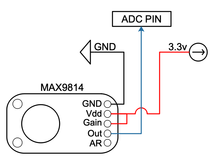
If you are using the MAX9814, you need to connect gain to vdd to set the gain to 40dB as the default 60db has far too much background noise.
Don't waste your money on cheapest hardware
Important: there are some inexpensive sound sensors you can buy from Aliexpress or elsewhere (such as LM393, KY-038 or KY-037). Typically these have an on/off output only (detecting "sound" or "silence"), sometimes there is an additional "analog data out" with very low quality. They may or may not work adequately. For more information on our microphone test results, see our Arduino Compatible Microphones document.
Use Squelch
If the LED's are active when the ambient volume is low while running volume only effects beginning with a single '*', you can increase the background noise filtering (or squelch) by navigating to the 'Config | Sound Settings' and increase the Squelch value. You can also make it more sensitive by lowering that Squelch value. In addition, there is a gain setting, which is required especially for the much lower signal level provided by the line-in configuration. Gain, Squelch and AGC are affecting all soundreactive, volumereactive and frequency (FFT) reactive effects.
good to know
Note 1: Do NOT connect input devices to 5V (or Vin). The power should be connected to the 3.3V pin.
Note 2: A piezo vibration sensor (from aliexpress) was successfully hooked up and tested. This piezo hack is not possible any more, as piezo impulses would be filtered out as random noise.
Note 3: On the ESP32, the default ADC pin is GPI36 (also known as VP), while the ESP8266 uses A0. On ESP32, any GPIO related to ADC1 can be used - see next note.
Note 4: If your ESP32 doesn't have pin 36, any of the other ADC1 (and not ADC2) pins should work.
Note 5: On the ESP32, the ADC and I2S pins are defined in audio_reactive.h. You can also select them in the sound settings UI.
Wiring
The following schematics are provided as an example only. There are many ways to achieve the same results. These are only a few of those ways.
| Microphone Wiring Example (MAX9814) | Line In Wiring Example |
|---|---|
 |
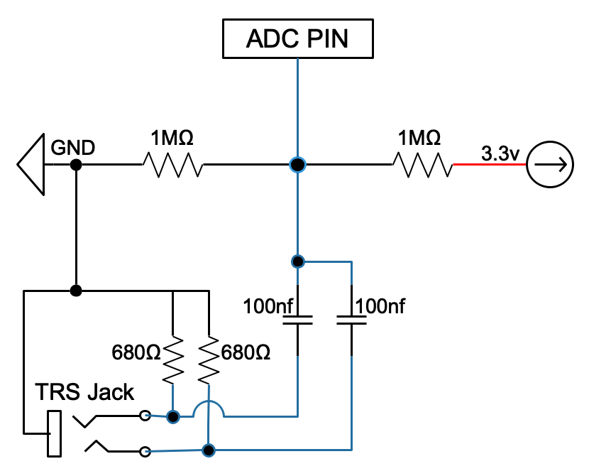 |
Some folks have mentioned that they don't need this line-in circuit, which is fine. Here's an explanation of that circuit.
The 680 ohm resistors provide termination so that you don't get reflection on the incoming signals. The 100nf capacitors remove any DC offset from the incoming signal. Remember that the ESP goes from 0V to 3.3V. Beyond that lay dragons. Finally, the 1M resistors provide DC centering of the incoming (now) AC only signal halfway between 0 and 3.3V.
Note 1: If you are just using a single L or R channel for the line-in, disconnect the capacitor for the other channel, or the resultant sample will be significantly reduced in amplitude.
Note 2: Providing a 'T' connector so that you can hear the music as it goes into the circuit is highly recommended. In the author's case, there was considerable static when the ESP32 was powered by the computer's USB port, but was fine when the ESP32 was powered by a USB powerbank.
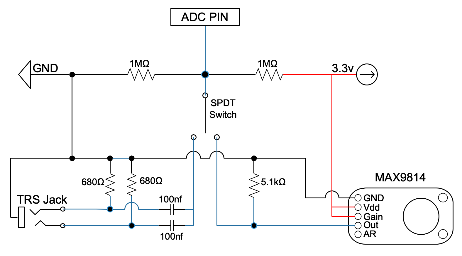
Dual Input Wiring
The following diagram shows one way of connecting a 3.5mm jack and an analog microphone to the ESP8266/32 while being able to change your desired input with a simple SPDT switch.
The left and right channels of the TRS Jack are connected together to sample both channels simultaneously as one channel.
Connect the output of the capacitor to the ADC pin for your board.
Pins Used
On the ESP32, the default ADC pin used is GPI36 (also known as VP), while the ESP8266 uses A0. Power is connected to the 3.3V pin. On ESP32 The ADC pin can be configured on the sound settings page; any GPIO associated with ADC1 (i.e. GPIO32 to GPI39) can be used.
Squelch
The volume and frequency reactive routines (starting with a single or double *), support a squelch or background noise suppression. This can be configured on the Sound Settings page.
Gain
Line-in signals are typically much lower than that of some of the microphones. Rather than use an auto gain function, you can manually adjust the gain from 1 to 255, which translate to a gain factor from 0.1 up to 6.5 gain. That's equivalent to a range of -20dB up to +16dB.
Problems Encountered
-
Spikes - We've often seen spikes when using an analog microphone in conjunction with WLED. There's an article that should shed light on the issue at ESP32 microcontroller generates noise on microphone.